

|
|
|
|
Soil resistivity is one of the most important factors in selecting a groundbed location. The number of anodes required, the length and diameter of the backfill column, the voltage rating of the rectifier and power cost are all influenced by soil resistivity. In general, the lowest and most uniform soil resistivity location with relation to depth should be utilized for a deep groundbed site.
Soil resistivity is measured in ohm-cm and is obtained by various means. A long-standing practice utilizes the Wenner four pin method. The deep groundbed designer should also call upon experience gained from other cathodic protection installations in the area. Earlier survey records often provide area resistivity. Many times the designer may obtain an estimate of average soil resistivity from a knowledge of rectifier output from the groundbed that is to be replaced. The following example illustrates this procedure.
Assume that it is desired to obtain soil resistivity in an area where another groundbed is operating at 22 volts and 40 amperes. In this technique, it is preferred to use operating data when the groundbed was first installed since the size and condition of the bed is known more precisely. It is known that the active column length of the operating bed is 49 m with a diameter of 15.2 cm. Experience has shown that the resistance of the backfill column to earth is approximately 85% of the total circuit resistance. In the example above the total circuit resistance by Ohm's law is:
Then the backfill to earth resistance RA is approximately:
RA = 0.55 W x 0.85 = 0.47 W
The H. B. Dwight relationship can be used to determine the backfill to earth resistance:
Where:
RA = groundbed resistance (ohm)
r = soil resistivity, (W m)
L = active bed length, (m)
r = active bed radius, (m)
Since RA is known, the above equation can be rearranged to solve for the resistivity:
The value of soil resistivity can be determined by substituting the known values for groundbed resistance indicated above as 0.47-ohm, the groundbed length and diameter.
The estimated value of 23.5 W m can then be used in the new design with reasonable confidence.
If existing groundbed data is not available, soil resistivity must be estimated by other techniques. Soil resistivity generally relate to the salinity or purity of the water or moisture, which historically has permeated the soil and remains there to one degree or another. The following broad guidelines relate USA areas and soil type conditions with its resistivity. (reference)
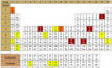
Area and/or Soil Type | Resistivity Range |
(W cm) | |
Brackish water lowlands, poor or slow drainage, coastal areas | 150 -1,200 |
Coastal plains, low elevation | 600 - 1,500 |
Central coastal areas, satisfactory to good drainage | 1,200 - 5,000 |
South central, Midwest and central, Farm and range lands | 3,500 - 10,000 |
West central desert plains, mountains | 5,000 - 25,000 |
Eastern and northeast high country, Excellent drainage, dry and arid | 10,000 - 25,000 |
![]()