


|
|
|
|
Many vessels that are candidate for conversion to FPSO service are fitted with hull mounted impressed current systems. For this reason most operators want to use the same system to protect the vessel in it's new role. If this is the proposed strategy the following areas must be carefully considered to avoid problems later on in the life.
The control reference electrode(s) monitor the potential of the hull at the area where they are located, this signal monitored by the controller built into the transformer rectifier power supply and the output current from the anode systems is adjusted to maintain the potential of the hull within an acceptable range. On a regular ship system, this will usually be somewhat close to the anode locations.
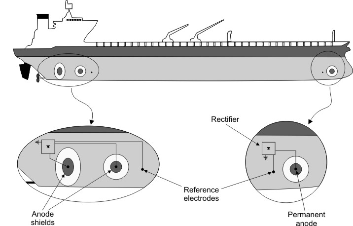
Typical ICCP design for a crude oil supertanker (reference)
This site selection is based on the desire to minimize the risk of coating damage at areas where the potential is expected to be more negative. When other subsea structures are introduced, particularly turret structures and risers, two problems can (and frequently do) arise;
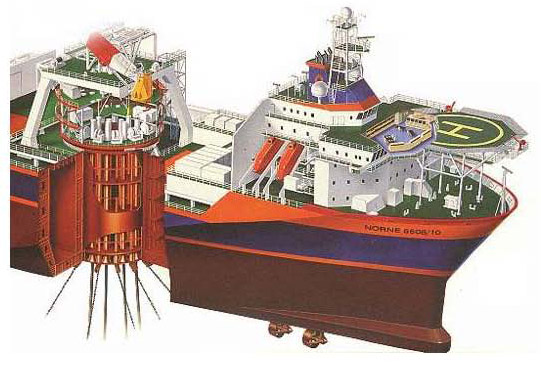
Typical FPSO Turret Detail (Courtesy Statoil)
It is recommended that additional reference electrodes are located at these critical areas with a facility to have one of them control the system if required. Existing electrodes can be used for monitoring rather than control. It is also a good idea to use dual element reference electrodes such as shown below. The standard electrodes provided are normally not expected to last 15 - 20 years. The dual element electrodes combine accuracy of silver/silver chloride (Ag/AgCl) with the long-term reliability of Zinc .
Permanent Dual Element Reference Electrode (source)
Hull mounted impressed current anodes have three major critical components.
The anode to supply cable connection and hull penetration
The dielectric shielding system
The active anode element and mounting
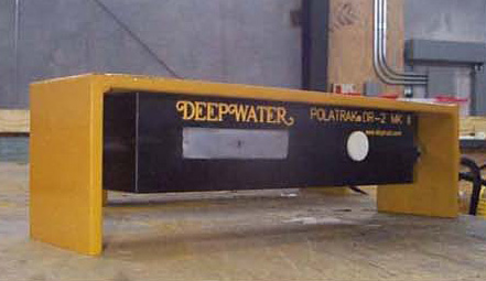
The most important area here is the dielectric shielding system (Fig. 6 below). This is applied to the area of the hull immediately behind and adjacent to the active anode element. In most systems this consists of two areas, a primary and secondary shield. The primary shield is usually a fiberglass or thermoplastic sheet that goes under the anode and extends about 1-2 feet (30 - 60 cm.) from the anode element in all directions. The shield is often mechanically fastened to the hull and a sealing/bonding compound introduced between the shield and the coated hull surface. The secondary shield is usually an area of high build epoxy or mastic coating that extends an additional distance 3-4 feet (90 - 120 cm.) beyond the primary shield. The integrity of this shield is critical if the CP system is to distribute protective current to all areas of the hull. Any damage to the shield will result in unacceptably high potentials on the exposed hull (if the anode is operated anywhere close to its rated current). This normally results in hydrogen evolution at the steel hull surface, which causes progressive disbondment failure of the shield to the point where the anode can no longer be operated. This area is virtually always in need of maintenance during 5 yearly dry dockings. Some systems have been observed where only a coating is used for both primary and secondary shield areas, varying only in applied thickness between the two sites, these systems should not be used.
Anode elements can usually be designed to last as long as required, so the protracted design life may not be a problem provided that the dielectric shield holds up. Problems can however arise, thus it is advisable to have the anode elements easily diver replaceable. While most manufacturers claim to have this facility, the writer is not aware of a successful offshore in-situ anode replacement having ever been completed.

Typical Hull Mounted ICCP Anode - Primary Dielectric Shield (Courtesy Deepwater)
See also: Fouling,FPSO, Ions in seawater,DO in seawater, Seawater scaling, Anti-fouling coatings
|  |
|