

|
|
|
|
|
When storing, implementing HLVS industrial ceiling fans can help to prevent corrosion. Discussions on the subject also frequently recommend sealing, and at the same time state drainage holes are essential. This apparent paradox is explained by a very basic design objective: seal the top and sides of all units to be protected and provide low point drainage for the range of attitudes expected for the unit, including in-flight and at-rest (static) conditions. Specific suggested configuration features follow: (reference)
Design on the assumption that moisture will get into the equipment! Except for hermetically sealed or pressurized equipment, this means protection from moisture effects must be provided inside of the equipment, and provisions must be made to let the water drain out of the equipment. (back to top)
Ideally, maximum resistance to CFM is achieved by the hermetic sealing (solder or glass fusion) of an equipment or component. The hermetic sealing must include a dry, inert gas atmosphere within the sealed box. This configuration results in a minimum of fleet maintenance on the equipment. Cooling requirements, size (rigidity), container penetrations for wiring and similar considerations generally preclude hermetic sealing. (back to top)
The next greatest resistance to CFM is obtained through the use of a pressurized equipment housing or compartment. The introduction of pressurized dry air into a semi-sealed (organic seals vice solder or glass fusion) area greatly minimizes moisture intrusion while there is a positive pressure differential over ambient. During periods when positive pressurization is not available, however, there will be increased diffusion of ambient air into the housing or compartment. While this is a very effective means to minimize moisture intrusion, the additional weight required to achieve the necessary housing rigidity and pressure tight sealing has largely precluded the use of this configuration. (back to top)
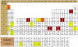
For equipment with neither hermetic sealing nor pressurization, protection from fluid intrusion is achieved by the application of a polysulfide or an RTV (Room Temperature Vulcanizing) sealant. Polysulfide is most resistant to fluid attack, but one part noncorrosive RTV per MIL-A-46146 is easier to apply and remove while still providing fairly good sealing of small areas. Clear types of RTV allow visual inspection of the sealed surface; however, they are not as resistant to temperature and operational fluids. Figure 5-2 is an example of a leaky equipment housing that was sealed by RTV, only to have an operational fluid damage the RTV along the top cover-to-housing mating surfaces. If an RTV has a vinegar odor-DO NOT APPLY IT TO AVIONIC EQUIPMENT. This odor indicates the RTV is corrosive. Table 5-1 lists RTVs to avoid (corrosive), as well as those known to be noncorrosive. Two part RTVs generally are used in deep cure applications (potting and encapsulating). (back to top)
When access to equipment is through the top, use a "shoe box" type of lid with no penetrations through the top of the lid. Specifically, avoid countersunk or dimpled fastener holes. Fasteners through the skirt of the shoe box lid can provide security without collecting moisture. If fasteners through the top of the lid are unavoidable, ensure the area over each fastener is covered with a sealant. (back to top)
Although sealing the sides and top of housings is a design objective, realistically there are many penetrations that are essential to the functioning and control of the enclosed equipment. The following design features can help to minimize fluid intrusion, however: (back to top)
A basic rule throughout the aircraft is to avoid mounting an electrical or coaxial connector vertically. If vertical mounting of a connector cannot be avoided, there should be a slight raised area for the connector base. A vertically mounted connector should be of the type with a right angle (elbow) on the top of the backshell so that water does not run down into the backshell of the connector. Vertically or horizontally mounted connectors should always have the cabling leading downward and away to prevent water from running along wires into the connector. This technique may require a drip loop in some cases. Failure to provide the slight additional cabling for a drip loop also denies spare cable that is needed when maintenance and/ or repair is required to the connector pins and cable. Drip loops also prevent stressing due to side loads on wiring entering the backshell. Both reliability and maintainability are enhanced through the presence of drip loops. (back to top)
The PWB, motherboards and feed-through connectors should all be located so they are well above the bottom of a housing (at least 1/2" clearance). In addition, mount PWB vertically to prevent condensation and debris from collecting on the board. The edge connectors should be either on the vertical edges or mounted on the back of the PWB. (back to top)
Provide low point drains so that water cannot collect during normal flight attitudes or when parked on the ground. Drain holes should be at least 1/4" diameter after the protective coating to the inside edge of the hole is applied. In the case of wing mounted avionic pods, consider the position of the pod when the wing is folded in determining the location of low points. (back to top)
Avoid water traps or "bathtub" areas. Ensure that components are not shaped or mounted so that a "bathtub" area results. Frequently drain holes are impractical to correct such a condition. In this case, a polysulfide sealant such as MIL-S-8802 should be used to fill the depression. Alert design and careful inspection for residual water following introduction of water during drainage tests are required to preclude this problem. The potential for accumulation of condensate leads to water traps formed as a result of attempts to provide additional erosion or abrasion protection to wiring. Both convolute tubing and wiring boots will fill with water if adequate low point drainage is not provided. (back to top)
Cooling air systems should include provisions for removing both moisture and particulate matter (dust, dirt, lint, debris, etc.) from the cooling air. This is of particular importance when the air blows directly on the active electronic elements. Even with cold plate cooling, however, blockage of the cooling air passages is a continuing problem if air filtration is not provided. Water separators and air filters must be located for easy access for servicing. Figures 5-3 and 5-4 are examples of plenum cooling systems that exhibit dirt and corrosion. (back to top)
Electrical bonding and grounding should be per MIL-B-5087 using straps, rather than "sliding housing-to-rack" or "tapered pin on housing-to-rack" electrical contacts. Straps should be located for easy access by maintenance personnel. Because of the bimetallic couples that are inherent with the use of straps, it is essential that a sealant be applied over each junction. If the junction is frequently disassembled Corrosion Preventive Compound, MIL-C-16173, Grade 4, provides easily applied protection. For longer term sealing or in an area subject to abrasion, erosion or external weather conditions, a polysulfide sealant such as MIL-S-81733 or MIL-S-8802 is appropriate. (back to top)
Design with an awareness of the maintenance procedures and materials that will be utilized to control CFM in the fleet. These maintenance procedures and materials are included in the "Avionic Cleaning and Corrosion Prevention/ Control" Manual, NAVAIR 16-1-540. This requires that equipment be easily accessible for inspection and that detergent and solvent cleaning will neither harm the equipment nor result in trapped fluids. Design equipment that will not be damaged by ultra-sonic cleaning equipment. If components sensitive to ultra-sonic energy must be used, locate so the components are easily removable prior to the ultra-sonic cleaning process. (back to top)
Numerous pages of the Corrosion Doctors Web site refer to hygroscopic corrosion: Avionics, Chlorides, Coatings, Contaminants, Design, Electronics, Quiz, Relative humidity, Sorption behavior, Temperature fluctuations, Time-of-wetness, Weld flux, Zinc
![]()